About Wedge Barriers
Wedge Barriers for Beginners
Table of ContentsThe Basic Principles Of Wedge Barriers Rumored Buzz on Wedge Barriers

Getting The Wedge Barriers To Work
g., springtime support 65 )might be dealt with to the end of the springtime rod 58 to allow compression of the springs 60. As the springs 60 are compressed in between the spring supports 62, the spring assembly 54 creates a force acting on the cam coupled to the springtime rod 58 in an instructions 66. For instance, the remaining force related to
the cam to deploy the wedge plate 16 might be supplied by an electromechanical actuator 84 or various other actuator. As such, the springtime setting up 54 and the actuator 84(e. g., electromechanical actuator)may operate with each other to translate the webcam and lift the wedge plate 16.
As stated over, the springtime assembly 54 puts in a consistent pressure on the cam, while the electromechanical actuator might be controlled to put in a variable pressure on the web cam, therefore allowing the lifting and decreasing( i. e., deploying and withdrawing )of the wedge plate 16. In specific embodiments, the continuous force applied by the spring setting up 54 might be adjustable. g., electromechanical actuator) is handicapped. As will be appreciated, the springtime assembly 54 may be covered and safeguarded from particles or other aspects by a cover plate(e. g., cover plate 68 displayed in FIG. 4) that may be considerably flush with the raised surface 38 of the structure 14. As pointed out above, in the deployed setting, the wedge plate 16 offers to block accessibility or traveling beyond the barrier 10. For instance, the barrier 10(e. g., the wedge plate 16 )might obstruct pedestrians or lorries from accessing a residential or commercial property or path. As reviewed over, the barrier 10 is affixed to the anchor 30 protected within the structure 14,
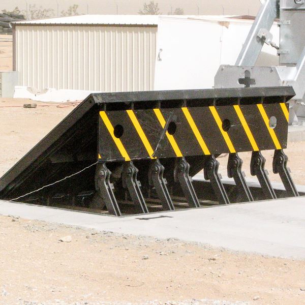
front braces 71. As a result, the linkage assemblies 72 may pivot and turn to allow the collapse and expansion of the link settings up 72 throughout retraction and release of the bather 10. The link assemblies 72 cause activity of the wedge plate 16 to be restricted. For example, if a vehicle is traveling in the direction of the released wedge plate 16(e. As an example, in one situation, the safety legs 86 may be prolonged duringmaintenance of the barrier 10. When the security legs 86 are deployed, the safety and security legs 86 support the weight of the wedge plate 16 against the surface area 12. Therefore, the lifting system 50 might be shut off, serviced, gotten rid of, replaced, and so forth. FIG. 5 is partial check my site perspective sight of a personification of the surface-mounted wedge-style barrier 10, showing the webcam 80 and the camera surface areas 82 of the training system 50. Specifically, 2 cam surface areas 82, which are described as reduced webcam surface areas 83, are positioned listed below the webcam 80. The lower webcam surface areas 83 may be repaired to the surface area 12 (e. As an example, the reduced camera surface areas 83 and the mounting plate 85 may create a solitary item that is protected to the support 30 by bolts or other mechanical bolts. Furthermore, two camera surfaces 82, which are described as upper camera surface areas 87, are positioned over the web cam 80 and coupled to (e. In various other personifications, interfering layers or plates might be positioned between the surface area 12 and the lower cam surface areas 83 and/or the wedge plate 16 and the upper web cam surfaces 87 As pointed out above, the More Bonuses camera
80 converts along the cam surface areas 82 when the wedge plate 16 is lifted from the retracted setting to the deployed placement. In addition, as discussed over, the springtime setting up 54 (see FIG. 3 )may offer a force acting on the camera 80 in the direction 102 via spring rod 58, which may reduce the force the electromechanical actuator 84 is called for to use to the camera i was reading this 80 in order to actuate and lift the wedge plate 16. 1 )to the released setting(see FIG. 4). As shown, the camera 80 consists of track wheels 104(e. g., rollers), which contact and convert along the cam surfaces 82 throughout operation.